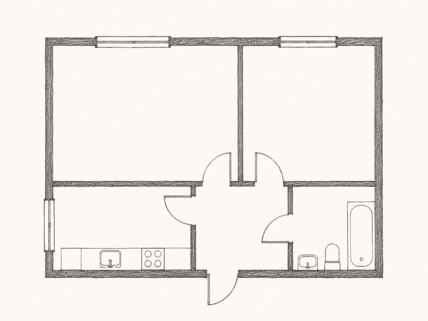
Drawing lines and construction lines
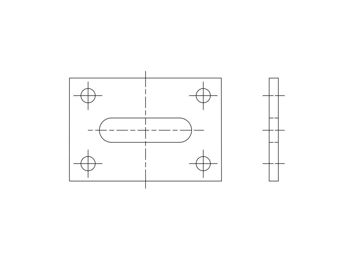
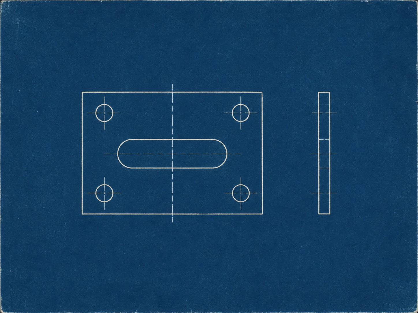
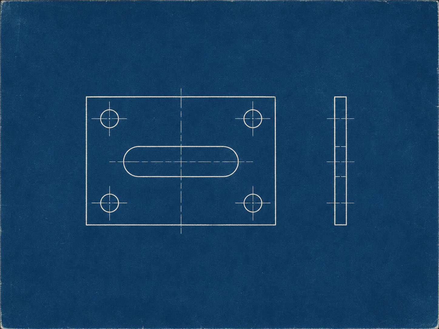
A blueprint may show object edges beside centerlines, projection lines, and dimension extensions. Look at the DXF to decide which marks represent the subject and which only explain the source drawing.
Keep the blueprint nearby while organizing the file. The conversion does not automatically know your intended layer structure or separate every construction mark from the geometry you want to retain.
Annotations are not verified dimensions
A blueprint can include numbers, symbols, and notes very close to its outlines. Compare the DXF labels with the source and rebuild important text when its meaning or placement matters.
Printed dimensions on a blueprint are not automatically applied as CAD constraints. Use reliable project measurements to size the DXF and check other distances, rather than treating every recognized mark as established geometry.
One image can contain several views
A blueprint may include a front view, side view, and a small section on the same sheet. Choose the area that is useful to your next task and keep the other views as references.
The DXF does not automatically assemble those views into a solid model. If you need a complete part, continue the modeling work with the blueprint, measured dimensions, and the relationships you define in CAD.
A readable scan is a better starting point
Folds, faded strokes, and heavy background texture can interrupt a blueprint outline. Use the clearest available scan, with the page flat and small details large enough to distinguish.
A higher resolution blueprint cannot restore information missing from the paper. Inspect the DXF around damaged areas and use another reliable source when a feature remains ambiguous. Rebuild only what the available references can support.