Wall boundaries and junctions
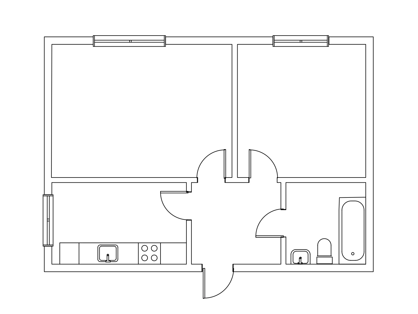
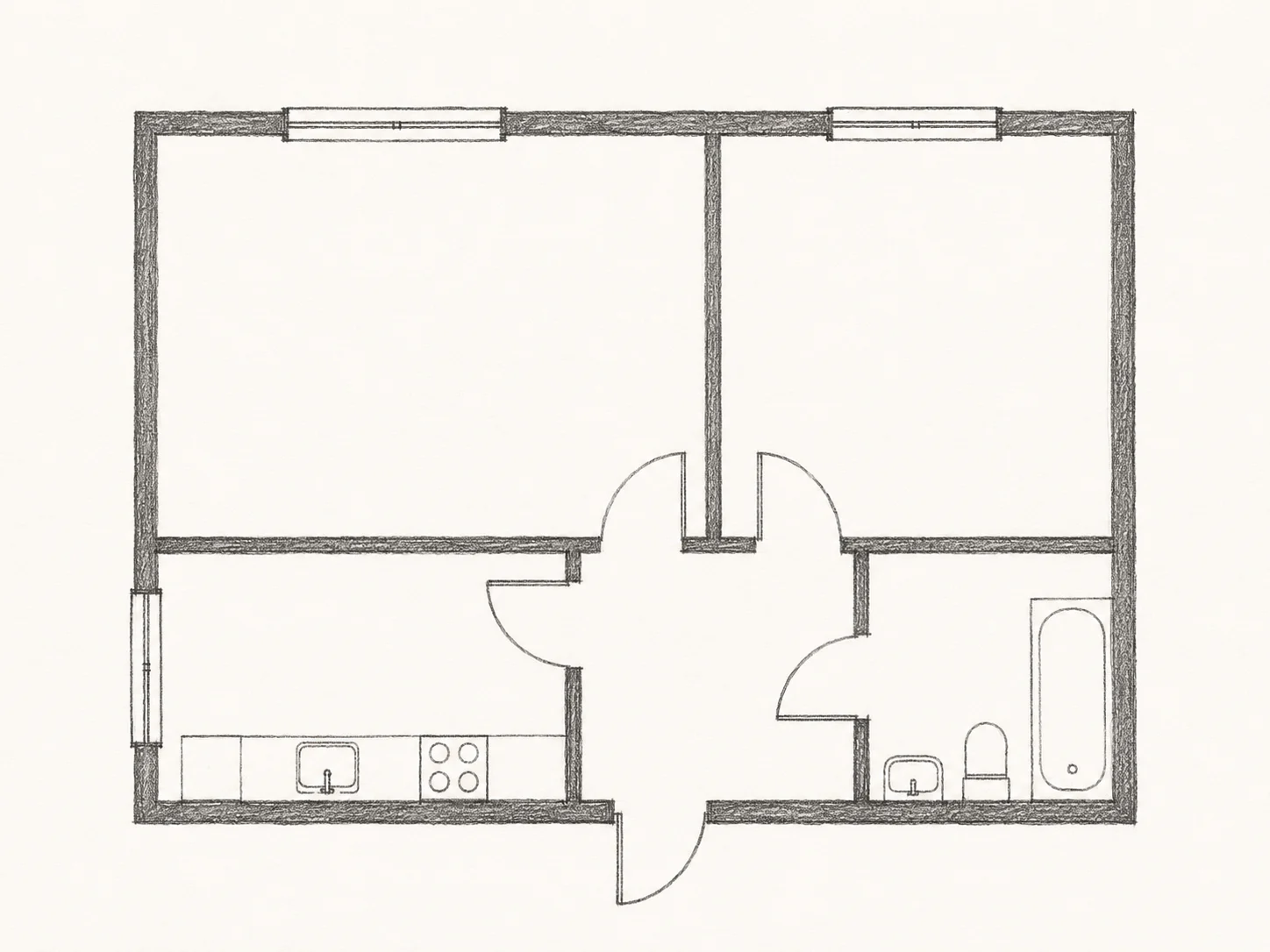
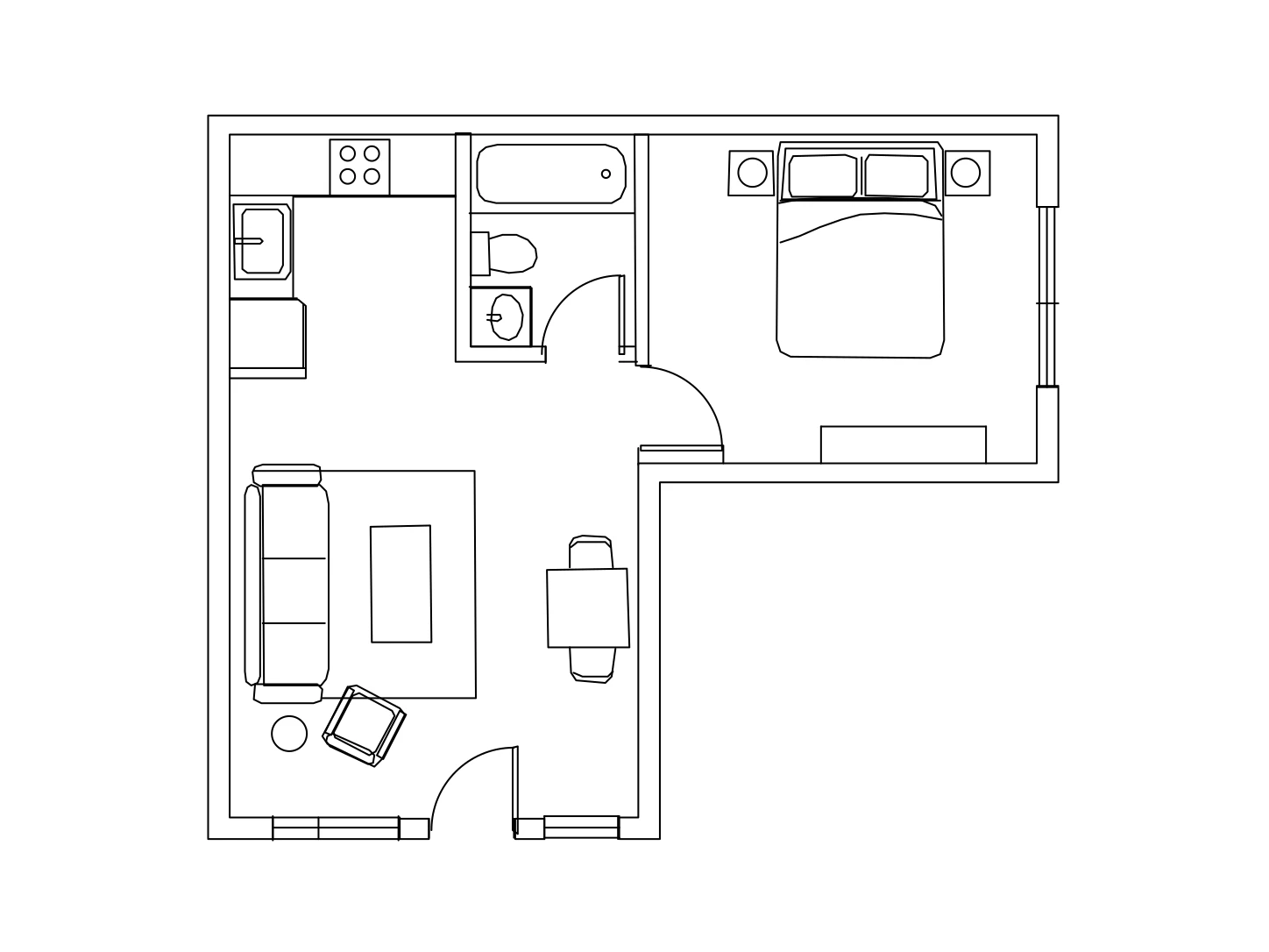
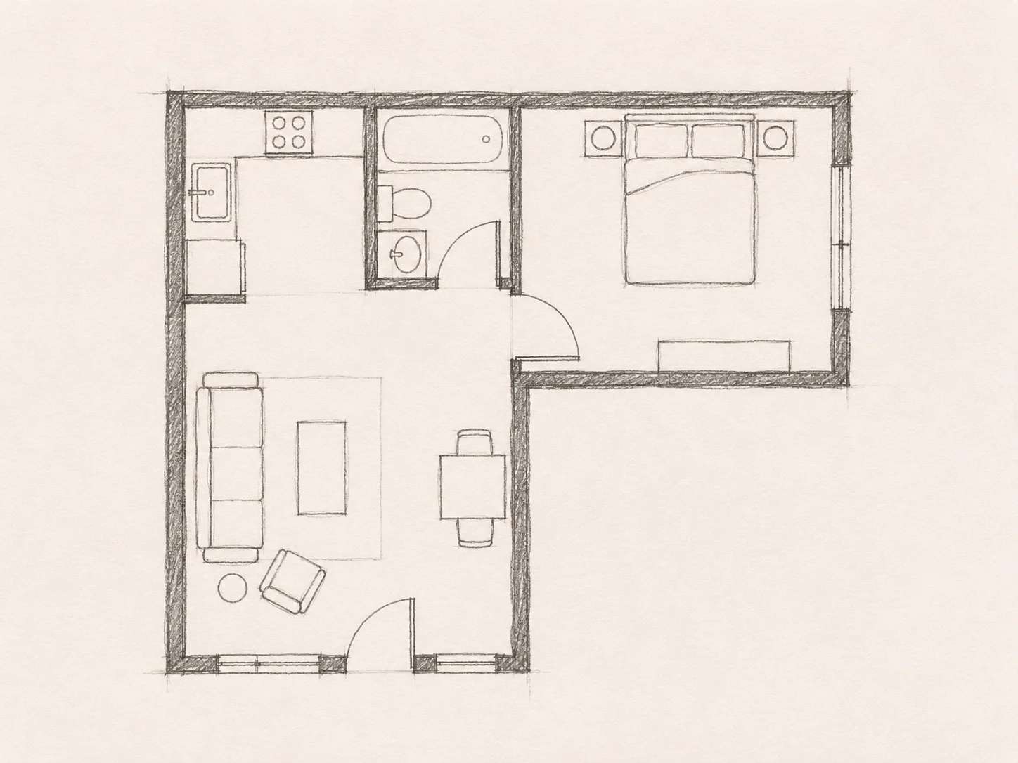
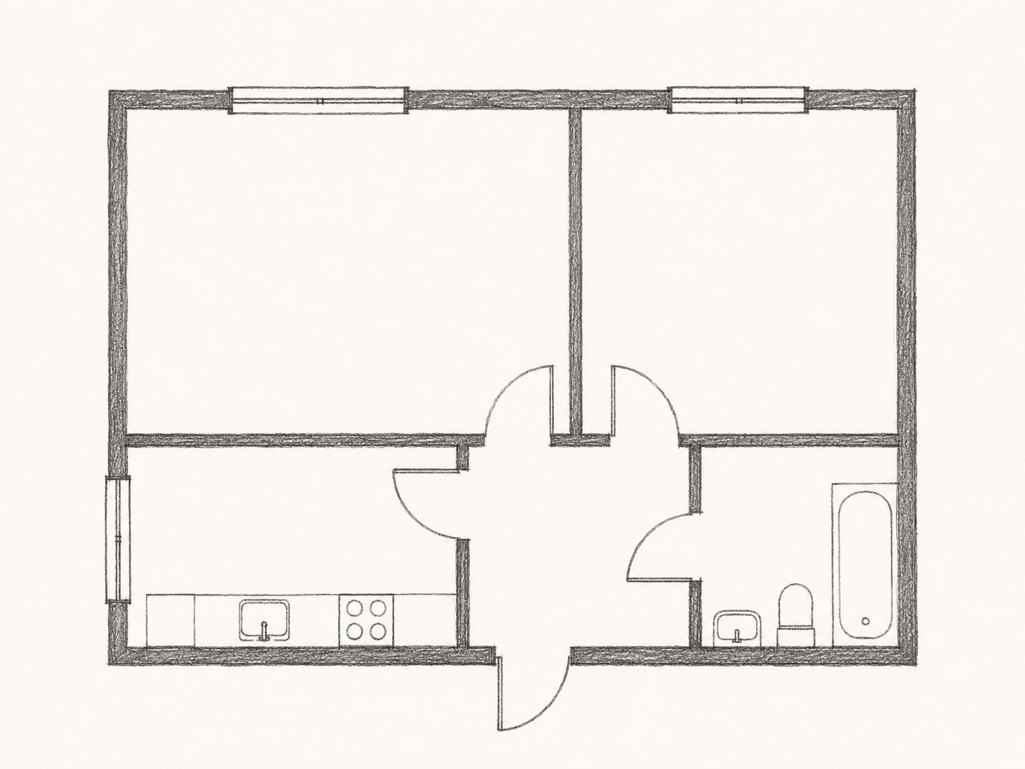
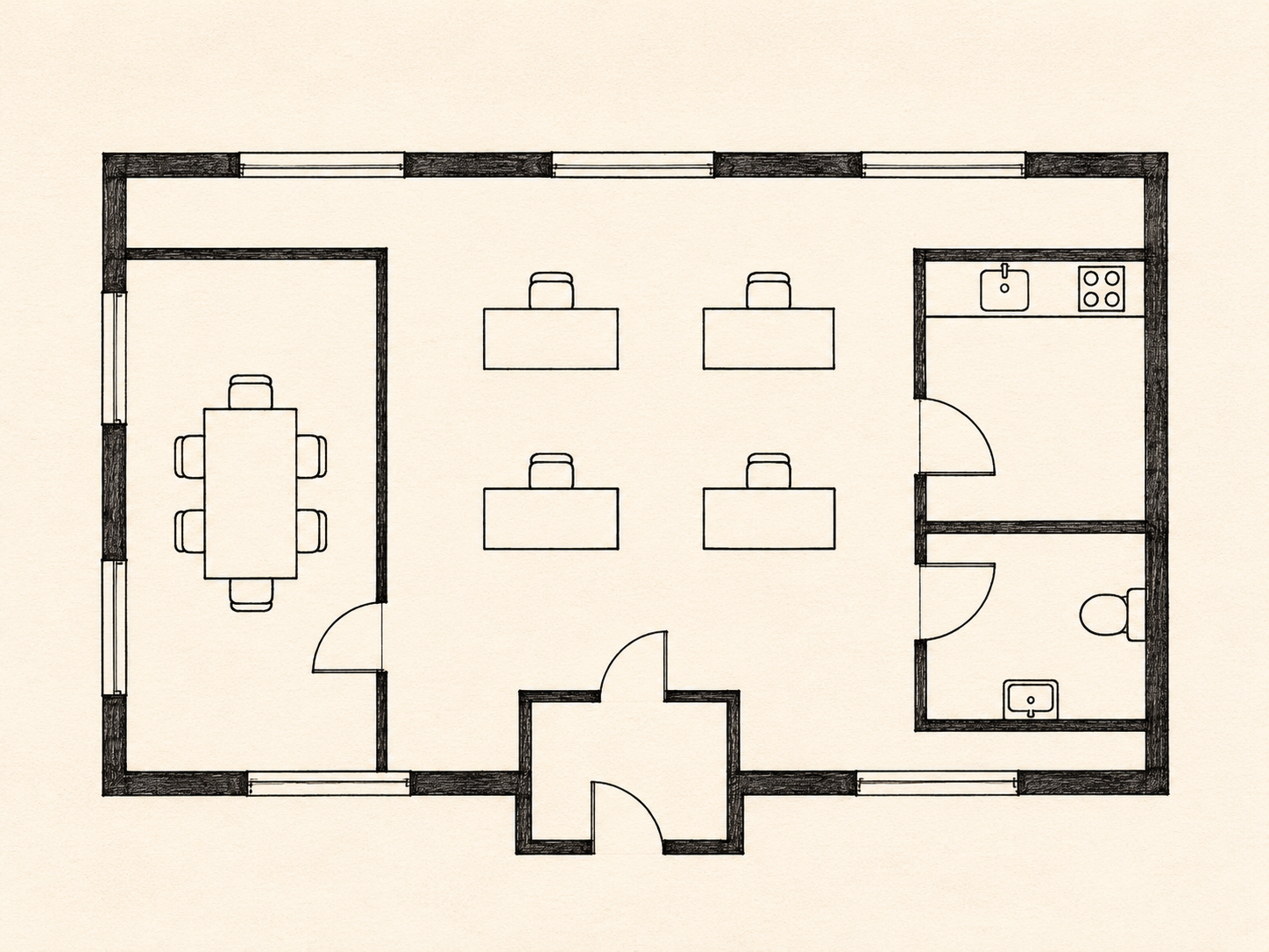
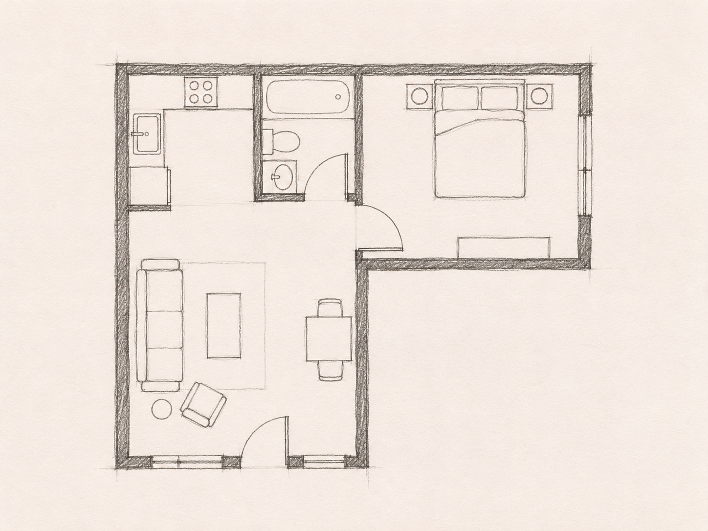
A floor plan may use double lines, thick strokes, or filled shapes to describe walls. Examine the DXF where these boundaries meet, especially around narrow corridors and small rooms.
Choose how to organize those outlines in your CAD editor. A floor plan to DXF conversion does not automatically turn the linework into architectural wall objects or recreate the original layer system.
Doors, windows, and circulation
Review the floor plan openings in relation to nearby walls. A door swing arc on the page is a graphic convention, not a guarantee that every detail will be interpreted correctly.
Check the DXF before using it to discuss circulation. A faint or overlapping mark on the source drawing may need redrawing so the opening reads clearly in your updated layout.
Labels and dimensions
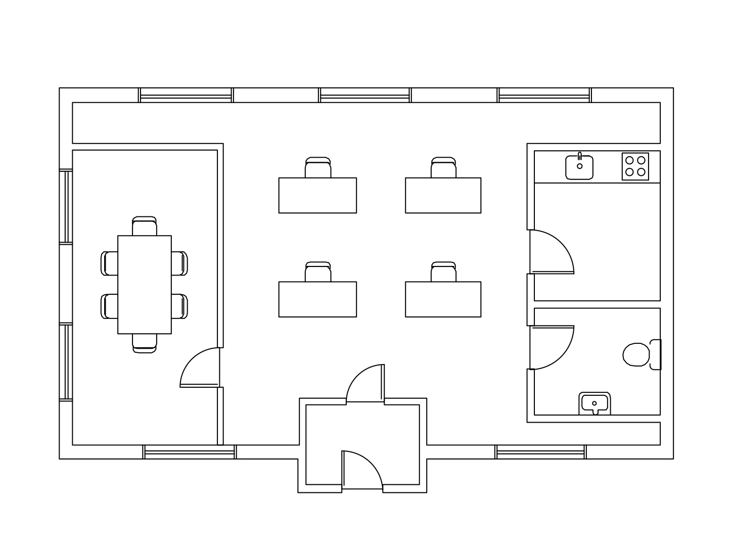
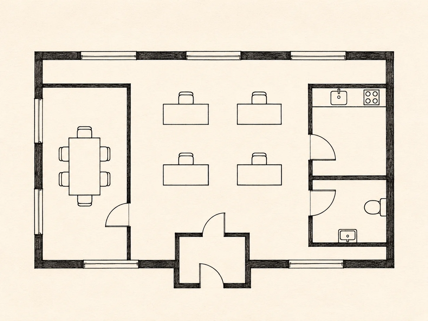
A floor plan can contain room names, furniture symbols, and dimension chains close to the main outlines. Check which elements you want to keep in the DXF and which are only background context.
Rebuild important annotations in your CAD application when needed. Text recognition and exact typography are not guaranteed, and a printed dimension on the drawing still needs checking against reliable project information.
Scale and an existing condition
Choose a known length to size the DXF, then check other distances across the floor plan. A resized scan or photographed drawing may have distortions that one reference dimension cannot fully resolve.
For an existing building, keep survey measurements alongside the floor plan. DXF geometry can support design work, but the reference does not verify current site conditions or structural details.